

 English
 العربية



ALSTOM MiCOM P40 Agile P141 Feeder Protection Relay
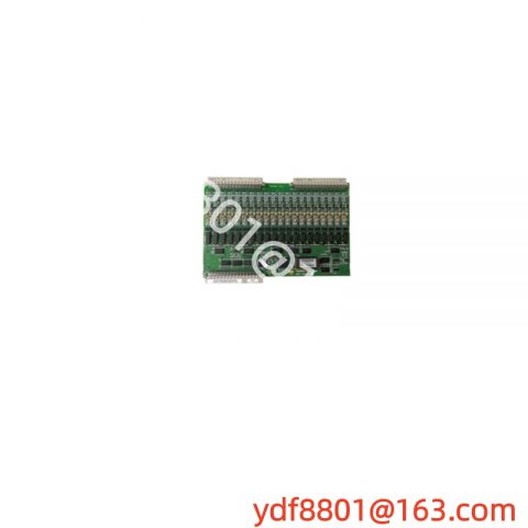
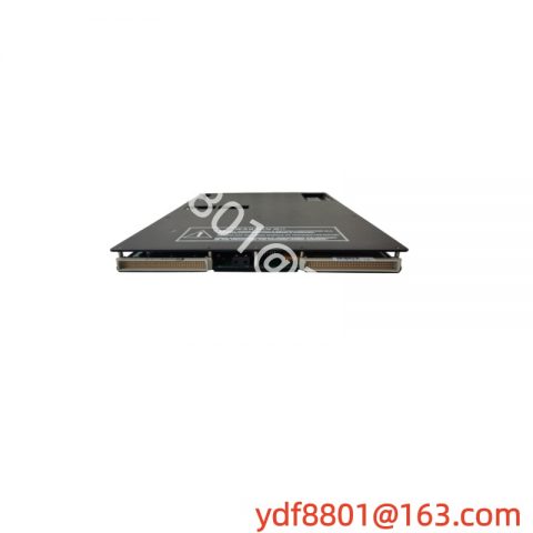
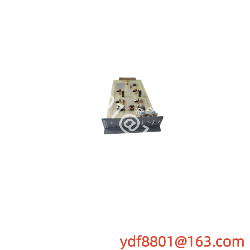
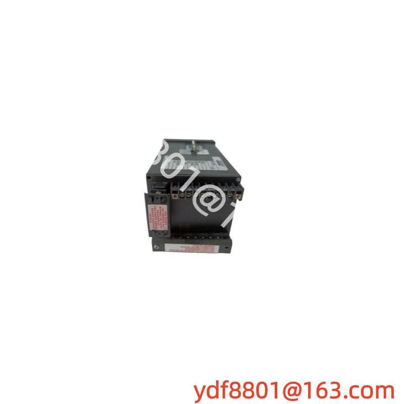
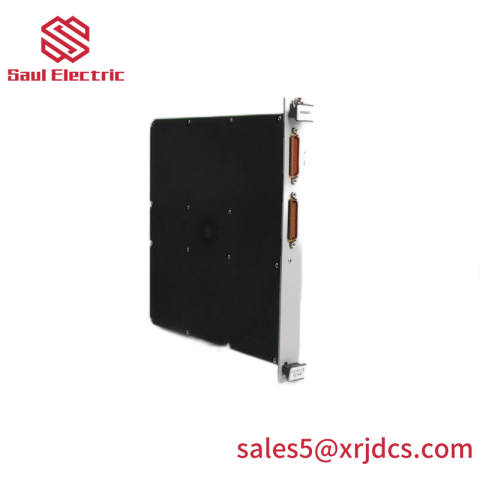
The Alstom MiCOM P40 is a plug-in control and communication unit for Alstom power plant and turbine control systems. It is built as a Eurocard-format circuit board that slides into a rack slot and mates with the backplane through a multi-pin connector at the rear edge. The front panel carries a handle for insertion and withdrawal, and the board is handled as a single replaceable unit during maintenance. It is supplied as a spare part for existing Alstom installations.
Key Specifications
- Manufacturer: Alstom
- Part Number: MiCOM P40
- Form Factor: Eurocard rack-mount plug-in board
- Mounting: Slides into a card slot in an Alstom control rack, engaged with the backplane connector
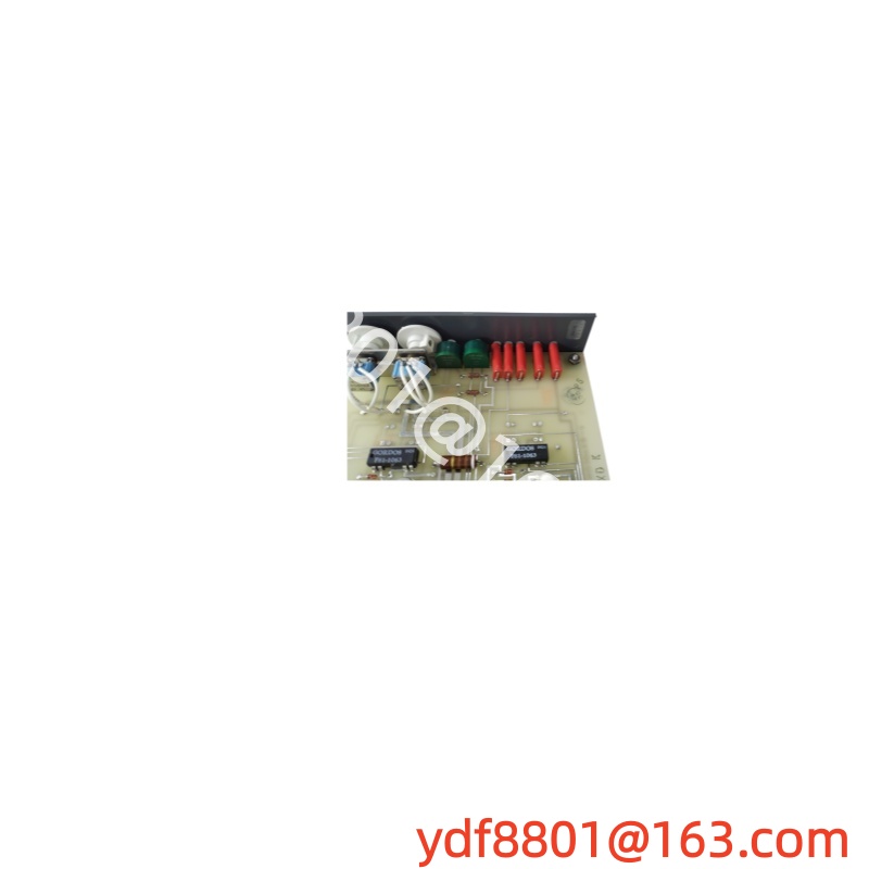
- Front Panel: Extraction handle, status indication on the front edge
- Rear Interface: Multi-pin backplane connector
- System: Alstom power plant and turbine control systems
- Country of Origin: France
Key Features
- Rack-Mounted Plug-In Construction: Standard Eurocard outline with front handle and rear backplane connector, made for slot-based installation and board-level replacement.
- Control and Communication Function: Serves as the control and communication unit within its Alstom system, carrying data between the rack and the system’s higher-level equipment.
- Board-Level Spare: Replaced as a complete unit, keeping the existing rack, wiring and backplane in place.
- Status Indication on the Front Edge: Front-panel indicators remain visible with the rack door closed, so the module’s state can be read without opening the cabinet.
- Original Alstom Build: Supplied as an Alstom part, matched to the systems that use this part number.
Typical Applications
- Thermal power plant control systems running Alstom equipment
- Gas turbine and steam turbine control cabinets
- Maintenance and spare-part replacement in existing Alstom installations
- Legacy Alstom control systems kept in service beyond their original design life
- Power generation plants holding critical spares for control racks
Ordering Notes
- Record the rack and slot: Note the cabinet designation, the rack number and the slot the module came from before removal.
- Note the neighboring modules: Adjacent card types identify the rack configuration and confirm the part number series.
- Read the board label: The part number and revision are printed on the board and on the front edge; record both when ordering a replacement.
- Check the rear connector: Match the backplane connector type and pin count against the slot before fitting.
- Keep the wiring record: Photograph the cabling and any front-panel connections before withdrawal, so the replacement goes back into the same arrangement.



There are no reviews yet.