

 English
 العربية



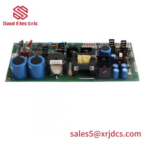

The BAILEY IMMFP01 Replacement Multi Function Processor is the first-generation Multi-Function Processor (MFP) module of the Bailey INFI 90® distributed control system. It is a standalone multi-loop controller that executes control logic, performs data acquisition, and exchanges information over the INFI-NET communication highway — the workhorse processor of INFI 90 cabinets.
Key Features
- Standalone multi-loop controller with data acquisition and information processing
- 32-bit processor (16-bit external bus) running at 16 MHz
- High-speed redundancy link supporting 1:1 redundant MFP pairs
- Three operating modes: execute, configure, and error
- Serial station-support port plus two general-purpose serial channels
- Direct memory access (DMA) circuitry for the I/O expander bus
- Interfaces to analog/digital I/O modules via the I/O expander bus
- Connects to INFI-NET via the module’s communication port / network interface modules
- Programmed with INFI 90 function-code configuration (function blocks; later MFP generations also support C, Basic, Batch, and Ladder)
Technical Specifications
- Type Designation: IMMFP01 (MFP01)
- Product Type: Multi-Function Processor Module (MFP)
- System: Bailey INFI 90® distributed control system
- Processor: 32-bit CPU (16-bit external bus), 16 MHz
- Memory: 256 KB RAM; 64 KB NVRAM (non-volatile); program storage in ROM (reference values per service data)
- Supply Voltage: +5 VDC @ 2 A (approx. 10 W typical)
- Serial Ports: 2 × RS-232-C, or 1 × RS-232-C + 1 × RS-485; up to 19.2 kbaud
- Station Support: Serial port for engineering station connection
- Redundancy: High-speed redundancy link (1:1 MFP redundant operation)
- Operating Modes: Execute / Configure / Error
- I/O Interface: I/O expander bus (auto/DMA) to INFI 90 I/O modules; supports up to 64 I/O modules (service data)
- Communication: INFI-NET highway via network interface modules (e.g., INNIS01)
- Mounting: One slot in a standard INFI 90 Module Mounting Unit (MMU)
- Ambient Temperature: 0…70 °C
- Dimensions: approx. 3.7 × 31.4 × 17.8 cm (H×W×D reference values)
- Origin: United States
Installation Notes
- De-energize the INFI 90 power system before inserting or removing the module from the MMU.
- Install the IMMFP01 into a processor slot of the Module Mounting Unit; seat the backplane connector fully and secure the module.
- For redundant operation, pair two MFPs via the redundancy link and configure the redundant pair in the engineering toolset.
- Connect the station-support serial port to the engineering workstation (up to 19.2 kbaud); terminate RS-485 links per network rules.
- Configure control logic in function-code language using the INFI 90 configuration software; download and place the processor in execute mode.
- Verify module status LEDs and error-mode indications after commissioning; confirm I/O expander bus communication with installed I/O modules.
Common Questions
What is the IMMFP01’s role in the INFI 90 system?
It is the control processor: it runs the configured control strategies (function codes), scans and conditions process I/O, and communicates with operator stations and other processors over INFI-NET.
Can the IMMFP01 be used redundantly?
Yes — the MFP supports a high-speed redundancy link for 1:1 redundant pairs, so a faulty processor transfers control to its partner without process interruption.
What programming language does it use?
INFI 90 MFP modules are configured in function-code language (function blocks). Later MFP generations (e.g., IMMFP03) additionally support C, Basic, Batch, and Ladder per the official instruction.
What power does the module need?
+5 V DC at approximately 2 A (about 10 W) from the INFI 90 backplane.


There are no reviews yet.